- Loading...
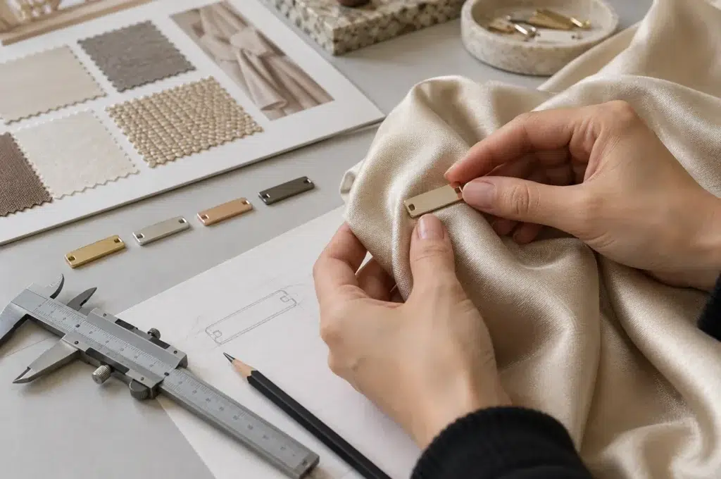
I have learned that attractive renderings can create false confidence when the geometry behind them is not tied to a controlled production drawing.
A capable custom fashion hardware supplier should support both 2D technical drawings and 3D CAD modeling. The formats control different risks: 2D defines measurable production requirements, while 3D clarifies form, fit, assembly, tooling, and manufacturability before sampling.
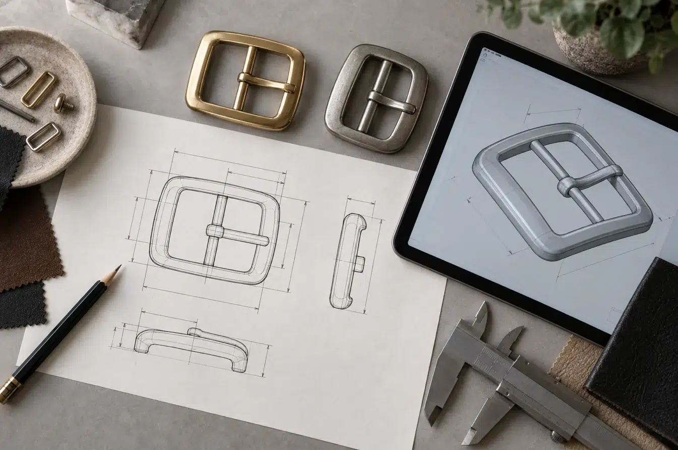
This does not mean that every washer, standard ring, or catalog component needs a new 3D development project. It means the supplier has enough engineering control to select the right format, create missing design data, keep revisions aligned, and carry an approved design into repeatable production.
What Roles Do 2D Drawings and 3D Models Play in Custom Fashion Hardware Development?
Treating 2D and 3D as competing formats creates gaps exactly where design data must move into tooling, inspection, and repeat production.
A 3D model defines nominal geometry and spatial relationships. A 2D drawing communicates critical dimensions, tolerances, materials, finishes, notes, and inspection requirements. Used together, they create a clearer development package than either format can provide alone.
Separate Geometry From Production Requirements
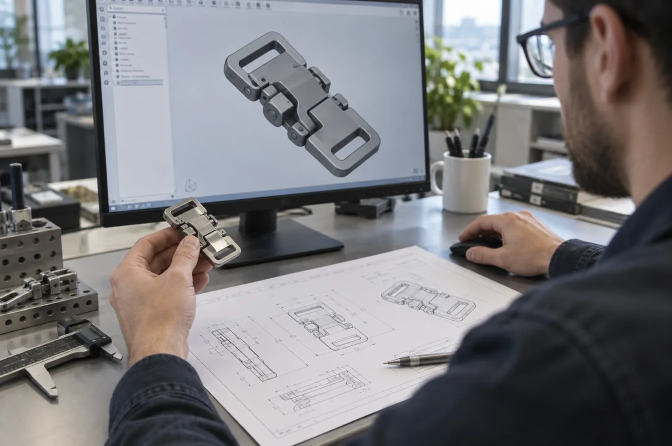
Three-dimensional CAD is the strongest format for communicating volume. It shows curved faces, sculpted logos, relief, recessed areas, hidden surfaces, wall sections, mating parts, and the relationship between front and back construction. It also allows the engineering team to rotate the component, create section views, check interference, and prepare geometry for prototyping or tooling.
A 2D drawing serves a different purpose. It draws attention to the requirements that must remain visible during quotation, production, and inspection. These can include overall dimensions, mounting-hole locations, material, surface finish, logo treatment, critical tolerances, assembly notes, and revision status. The drawing is easier to mark, compare, approve, and use as an inspection reference.
The strongest workflow assigns clear authority to each format. The 3D model can govern nominal geometry, while the 2D drawing controls specified dimensions and written requirements. If the two files conflict, the development procedure must state which document takes priority and how the discrepancy will be corrected before production.
| Development question | Primary 2D role | Primary 3D role |
|---|---|---|
| What is the component’s shape? | Shows standard views and sections | Defines the complete nominal form |
| Which dimensions are critical? | Identifies values, tolerances, and datums | Shows the related geometry and interfaces |
| How does the part connect? | Records mounting dimensions and notes | Reveals spatial fit and assembly relationships |
| How will the part be made? | Communicates material, finish, and process notes | Supports tooling and manufacturability review |
| How will output be checked? | Provides measurable inspection requirements | Supplies nominal geometry for comparison |
Match the Design Package to Product Risk
A low-risk flat logo plate may begin with vector artwork and a complete 2D drawing. The drawing can define length, width, thickness, corner radius, hole position, logo treatment, edge condition, and finish. Creating a complex 3D model for a simple flat part may add little value if the geometry is already unambiguous.
Three-dimensional capability becomes much more important when the component includes sculpted surfaces, curved profiles, multiple faces, deep relief, moving parts, assembled sections, hidden attachment features, or tooling-dependent geometry. Buckles, clasps, swivel hooks, turn locks, decorative closures, dimensional zipper pulls, and multi-part ornaments often contain relationships that cannot be judged reliably from a front view.
The supplier therefore needs both capabilities even when both are not used at the same depth for every item. A broad product range creates changing risk. The useful qualification standard is the ability to determine what information the component requires, not a rule that forces unnecessary modeling into every order.
What Product Information Should a 2D Technical Drawing Include?
Incomplete drawings invite assumptions, and those assumptions become difficult to detect once the first sample looks visually acceptable.
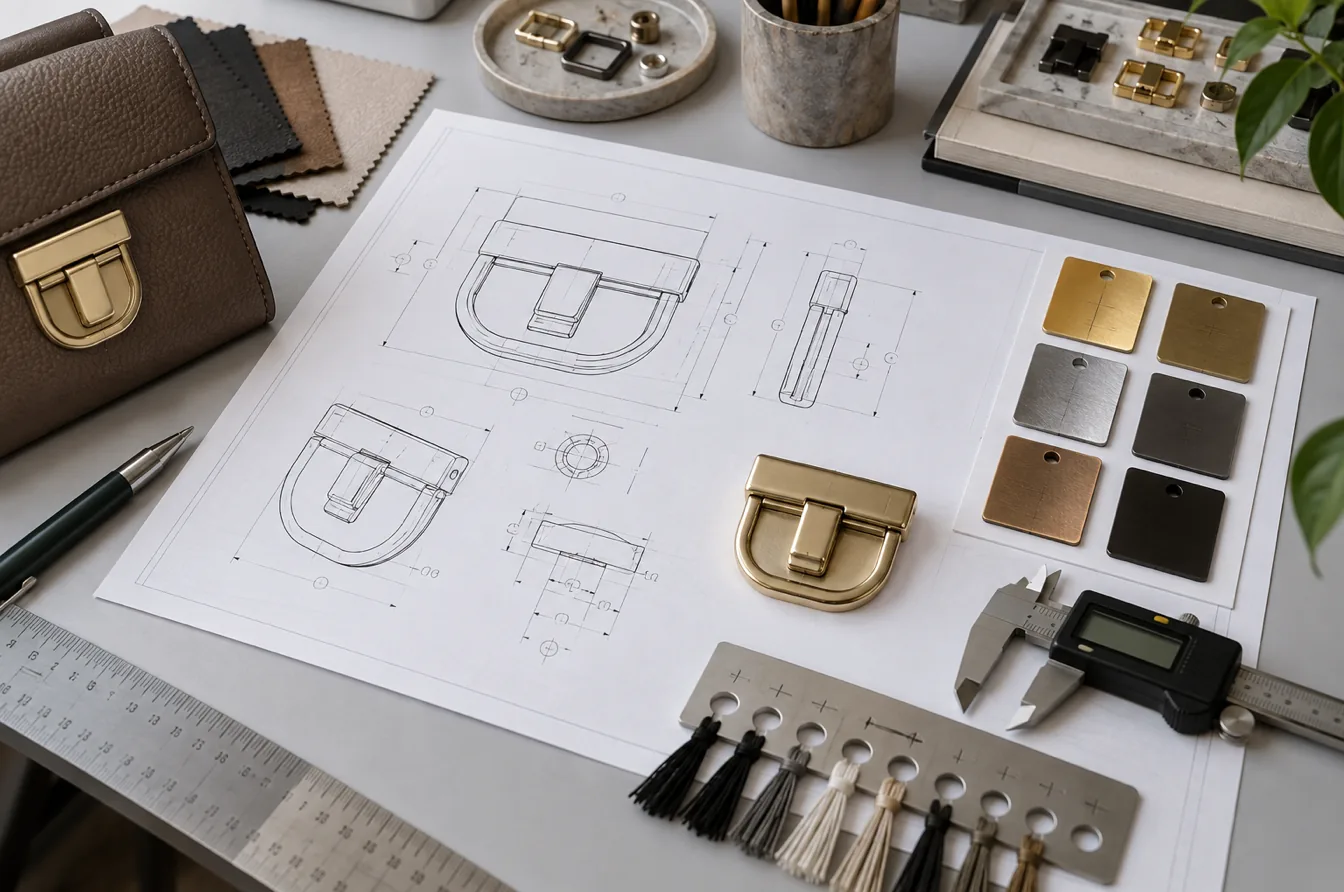
A production-ready 2D drawing should identify the part, revision, views, dimensions, critical tolerances, material, finish, logo treatment, attachment method, mating features, and inspection points. Every requirement that affects fit, appearance, function, or acceptance should be recorded clearly.
Define the Part Beyond Its Front View
Fashion hardware is often presented through its visible face, but production depends on the complete object. A useful drawing includes enough views and sections to explain front geometry, rear construction, thickness changes, recessed areas, posts, prongs, loops, screw points, rivet locations, sew-on holes, and other attachment details. A single perspective image is not a technical definition.
The drawing should also connect the part to its intended application. A buckle needs the actual strap width and thickness. A zipper pull needs the correct slider interface. A logo plate requires the substrate thickness and mounting method. A closure needs its mating component, engagement depth, and movement direction. These relationships determine whether the component functions after assembly, even when the isolated sample appears correct.
Material and surface instructions belong in the same controlled package. The base material, visible finish direction, texture, gloss, color reference, logo process, enamel or paint areas, and protected surfaces should be defined without relying on memory. A physical finish sample can remain the visual authority, while the drawing records where and how that finish applies.
| Drawing field | Information to define | Risk when omitted |
|---|---|---|
| Part identification | Part number, description, and revision | Files and samples become difficult to match |
| Geometry | Views, sections, dimensions, and thicknesses | Shape is interpreted differently by each team |
| Attachment | Holes, posts, prongs, loops, threads, or rivet points | Hardware does not fit the final product |
| Material | Base metal and relevant construction notes | Cost, weight, forming, and finish behavior change |
| Surface requirement | Finish areas, texture, gloss, color, and logo treatment | Appearance varies between samples and production |
| Inspection | Critical characteristics and checking method | Acceptance decisions become subjective |
Use Tolerances as Functional Decisions
A tolerance is not a general sign of quality. It defines how much controlled variation a feature can accept while the component still fits, moves, assembles, and looks correct. Applying unnecessarily tight tolerances to every dimension can increase tooling, processing, sorting, and inspection effort without improving the product.
Critical tolerances should concentrate on functional interfaces. Examples include post spacing, hole position, strap openings, hinge alignment, latch engagement, mating diameters, overall thickness at an assembly point, and clearance around moving elements. Decorative dimensions may allow more variation when that variation does not affect the approved visual standard.
The drawing should distinguish critical dimensions from reference dimensions. It should also define the relationship between the nominal 3D geometry and the values selected for inspection. This prevents the inspection team from measuring convenient features while missing the interfaces that determine actual performance.
Tolerance decisions are especially revealing during supplier evaluation. A capable engineering team asks which features drive fit and function, identifies realistic manufacturing variation, and proposes an inspection approach. A weak response either ignores tolerances or applies restrictive values everywhere without explaining their purpose.
How Does 3D Modeling Help Evaluate Form, Fit, Assembly, and Manufacturability Before Sampling?
A rendering can confirm visual direction, but production-ready CAD must expose the hidden geometry that controls tooling, attachment, movement, and repeatability.
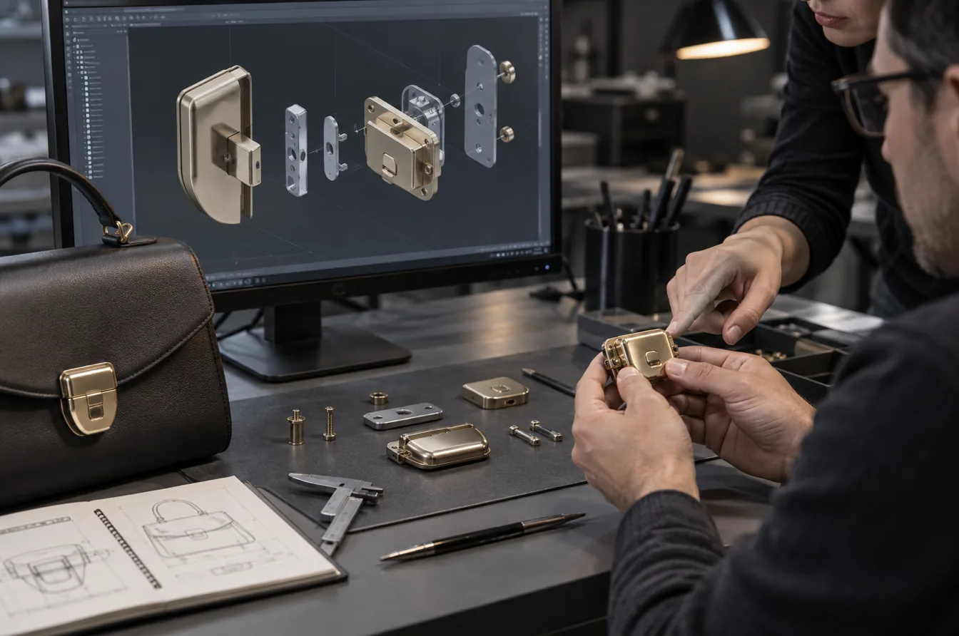
Three-dimensional modeling allows form, mating relationships, clearances, wall sections, undercuts, release direction, assembly sequence, and tooling access to be reviewed before physical sampling. Its value comes from manufacturing-aware analysis, not from visual presentation alone.
Review Shape, Interfaces, and Hidden Geometry
Complex fashion hardware usually fails at an interface rather than on its most visible surface. A clasp may look balanced but bind during rotation. A buckle may match the sketch but pinch the strap because the opening ignores material thickness. A decorative plate may reproduce the logo while its posts conflict with seams or reinforcement layers. Three-dimensional review makes these relationships easier to examine before metal is cut.
The model should include the component’s rear construction and mating parts wherever possible. Strap sections, leather tabs, fabric layers, sliders, springs, pins, screws, and adjacent hardware can be represented at the required level of detail. Assembly motion can then be reviewed for collision, insufficient clearance, inaccessible fasteners, or weak connection areas.
Manufacturability review applies the intended process to the geometry. Die-cast parts may require attention to release direction, parting strategy, wall transitions, thin features, and finishing access. Stamped parts require realistic material thickness, bend conditions, formed features, and tool access. Machined or fabricated parts create different questions. The CAD model becomes valuable when these process limits produce specific, documented design decisions.
| 3D review area | Question to resolve | Typical design consequence |
|---|---|---|
| Form | Does the volume match the intended silhouette and visual weight? | Curves, relief, or proportions are adjusted |
| Fit | Do openings and interfaces match the real mating components? | Clearances or mating dimensions are revised |
| Assembly | Can parts be installed and moved without interference? | Access, sequence, or connection geometry changes |
| Tooling | Can the geometry be formed and released as intended? | Undercuts, parting, or wall transitions are modified |
| Finishing | Can visible and recessed areas be polished and finished consistently? | Recess depth, edge form, or access is improved |
Use Digital Prototypes Before Committing to Tooling
A digital model creates a practical bridge between the design review and an early physical prototype. Depending on the product and manufacturing route, the model can support a resin print, wax pattern, machined sample, or another geometry-focused prototype. The purpose is to confirm scale, silhouette, attachment, assembly, movement, and interaction with the final product before production tooling is fixed.
Prototype material does not need to imitate every property of production metal to answer useful questions. A dimensional model can reveal whether a logo feels too heavy, a puller is difficult to grip, a clasp is oversized, or a mounting system conflicts with the final material. Functional conclusions should remain limited when prototype material or construction differs from production intent.
Geometry approval and finish approval should remain separate. CAD can define the surfaces and the locations of finish treatments, but it cannot prove final plating tone, polishing character, enamel appearance, tactile weight, spring force, or production movement. A physical production-intent sample remains necessary for these decisions. Digital work reduces avoidable structural uncertainty; it does not replace material and finish validation.
When Should 2D Drawings and 3D Models Be Updated During Sampling and Design Revisions?
Sampling loses control when accepted changes remain in messages, marked photographs, or isolated files instead of returning to the approved design package.
Both 2D drawings and 3D models should be updated whenever an accepted change affects geometry, fit, material, finish location, attachment, tolerances, tooling, or inspection. Matching revision identifiers should connect every sample to the correct design state.
Maintain One Controlled Design Authority
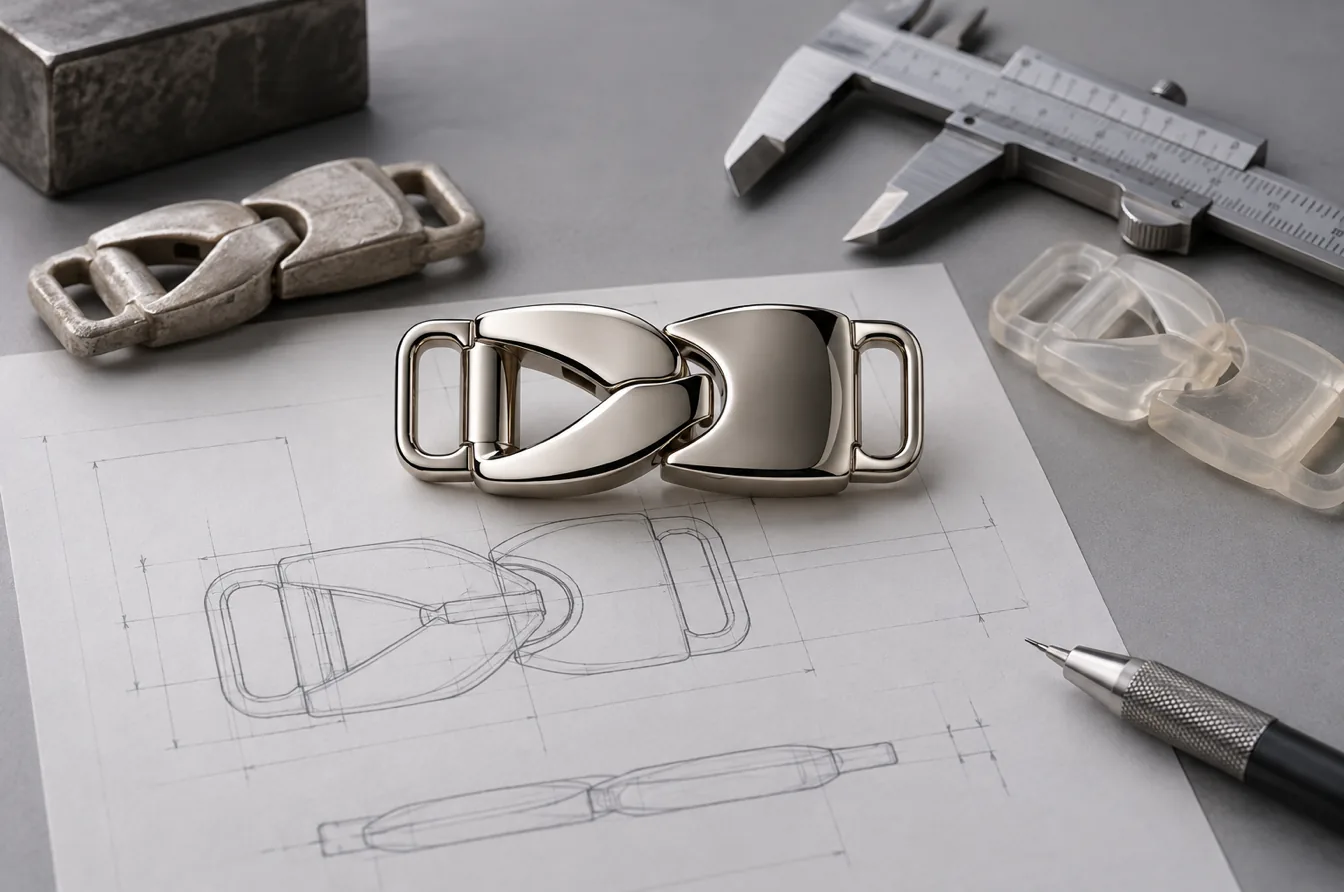
The development team should establish which file governs each type of information. A common structure uses the 3D model as the master for nominal geometry and the 2D drawing as the master for controlled dimensions, tolerances, material, finish, notes, and inspection requirements. This arrangement works only when the files are deliberately synchronized.
Every issued package needs a part number, revision code, issue date, and approval status. The physical sample should carry or reference the same identifiers. When a marked photograph or meeting note results in an accepted change, that change must be incorporated into the model or drawing before the next stage begins. Otherwise, the factory may reproduce the sample while the purchasing and inspection teams continue using obsolete data.
Conflicts should never be resolved through assumption. If a drawing dimension differs from the model, tooling and production should stop at that point until the authority is confirmed and both files are corrected. The same discipline applies when a hand-adjusted sample is accepted. A manual improvement that is not translated into geometry, tooling, or process instructions cannot be reproduced reliably.
| Development milestone | Required update | Approval evidence |
|---|---|---|
| Initial engineering review | Open questions and proposed geometry | Reviewed concept package |
| Geometry approval | Controlled 3D model and key 2D dimensions | Dated geometry approval |
| Functional sample | Fit, movement, and attachment corrections | Functional evaluation record |
| Finish sample | Finish areas and visible acceptance details | Controlled finish reference |
| Tooling trial | Tool-driven geometry and process changes | Updated production package |
| Pre-production release | Final model, drawing, sample, and inspection points | Release approval with matching revision |
Separate Sample Purposes and Lock Decisions Progressively
Each sample round should answer defined questions. An early form model can resolve size and proportion. A functional prototype can resolve mating, movement, and attachment. A finish sample can resolve color, gloss, texture, and logo clarity. A pre-production sample should demonstrate the combined result using a production-intent route.
Changing several unrelated variables in one sample makes cause and effect difficult to understand. A dimensional correction should not quietly introduce a new material or finish interpretation. Each review should identify which characteristics remain open, which are locked, what changed, why it changed, and which current documents contain the decision.
The 3D model needs an update when nominal geometry changes. The 2D drawing needs an update when dimensions, tolerances, notes, materials, finish locations, inspection requirements, or revision information changes. Many revisions affect both. The next sample request should reference the updated package rather than relying on an earlier sample plus a list of informal exceptions.
Progressive locking protects later stages. Once tooling begins, uncontrolled geometry changes create avoidable rework. Once finish development begins, changing the underlying surface can alter the visual result. Once production is released, inspection cannot operate effectively if the accepted sample and controlled documents represent different design states.
How Can Sourcing Teams Evaluate a Supplier’s 2D and 3D Modeling Capabilities?
Software lists and polished renderings reveal very little about whether design data remains accurate from the first brief through production inspection.
Capability is demonstrated by a controlled project trail: input review, production-ready CAD, technical drawings, manufacturability feedback, documented revisions, representative samples, and inspection criteria that remain connected to the approved design.
Examine Evidence From a Real Development Sequence
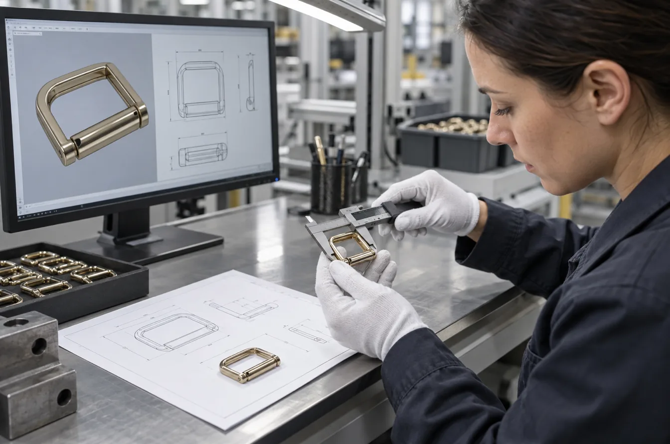
A practical evaluation begins with a comparable project rather than a general presentation. Sensitive brand information can be removed, but the supplier should still be able to show how a sketch, reference sample, or artwork file became controlled geometry. The explanation should include the questions raised, the manufacturing risks found, the proposed changes, the approval stages, and the final connection between design data and the physical component.
The review should distinguish visualization from engineering. A rendering demonstrates communication skill, but it does not prove that the underlying model is scaled correctly, editable, toolable, and connected to a drawing. A stronger example includes section views, rear construction, mating geometry, manufacturing considerations, and revision history. It also shows what changed between the first proposal and the approved sample.
A small trial project can reveal more than a long questionnaire. The same brief can be issued to candidate suppliers with a defined request for a 3D concept, a dimensioned 2D drawing, identified risks, and a revision after feedback. The quality of the questions, assumptions, file organization, and corrective proposal provides direct evidence of working method.
| Capability area | Strong evidence | Weak signal |
|---|---|---|
| Input review | Missing information and conflicts are identified | Every request is accepted without questions |
| 3D engineering | Editable production geometry with sections and interfaces | Presentation render with no technical structure |
| 2D documentation | Dimensions, tolerances, notes, and revision control | Screenshot or outline with no production details |
| Manufacturability | Risks are linked to process and corrective options | Generic statement that the design is possible |
| Revision control | Matching identifiers across files and samples | Changes remain scattered across messages |
| Production connection | Approved data appears in tooling and inspection | CAD work ends after client presentation |
Connect Modeling Capability to Production Control
The engineering team should be able to explain how CAD data enters prototyping, tooling, production, and inspection. Neutral 3D exchange files and readable 2D documents improve continuity between different systems, but file formats alone do not establish capability. The important evidence is whether geometry, dimensions, notes, and revisions remain consistent after every handoff.
Responsibility also needs to be visible. Modeling may be performed internally or through a controlled engineering partner. Either arrangement can work when the supplier owns communication, technical review, revision accuracy, confidentiality, and corrective action. An undisclosed handoff is riskier because questions can lose context and revisions can be applied to only one file.
Inspection closes the loop. Critical characteristics identified during development should appear in the sample review and production inspection method. If CAD identifies a mating gap, mounting distance, hinge axis, or critical profile, the production team needs a practical way to verify it. A modeling department disconnected from quality control produces attractive development material but weak production control.
For a supplier covering varied custom fashion hardware, combined 2D and 3D capability is therefore a meaningful qualification signal. The strongest evidence is not a claim that both services are available. It is a repeatable sequence that converts design intent into manufacturable geometry, controlled documentation, approved samples, and measurable production output.
Conclusion
For varied custom fashion hardware, both capabilities are a practical supplier standard when they connect design intent, manufacturability, sampling, revision control, and repeatable production.